



A knapsack sprayer diagram shows the three groups of parts that every backpack sprayer is built from: the parts that carry the load, the parts that build pressure, and the parts that deliver the spray. This knapsack sprayer diagram guide labels those parts on our own manual and engine-driven backpack sprayers, using the part names from our catalog where it gives them, so that a buyer, a technician or a student can name a component and order the right spare.
- Manual sprayer: tank, hand lever and pump with a leather cup, hose, shut-off handle, lance and nozzles, shoulder straps.
- Electric knapsack sprayer: tank, battery and water pump in the base, power switch and charging socket, hose, switch water handle, spray rod and nozzle.
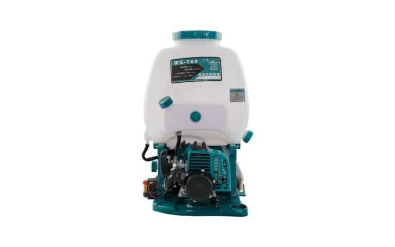
- Knapsack power sprayer: tank, small gasoline (petrol) engine, aluminum plunger pump, switch box, hose and brass spray gun, strap and cushion.
- Parts to check first when pressure drops: the plunger and its seals, the valves, the nozzle, the gaskets and the strainer.

What Does a Knapsack Sprayer Diagram Show?
Any knapsack sprayer diagram divides the machine into a tank carried on the operator’s back, a pump that pressurizes the liquid, and a hose and spray gun that direct it at the crop. The difference between the two types is in the middle group. On a manual sprayer the operator pumps with a hand lever, so the pressure rises and fades with every stroke. On a knapsack power sprayer a small gasoline (petrol) engine drives a plunger pump, the pressure stays constant, and both hands stay on the gun.
Reading a knapsack sprayer diagram in that order, load, pressure, delivery, makes the rest of the machine easy to follow: everything on the frame either carries weight, makes pressure or carries liquid. Load parts such as straps and cushions wear on the outside; pressure parts such as the plunger and its seals wear on the inside; delivery parts such as nozzles and gaskets block or leak. Our guide on how to use a knapsack sprayer covers assembly and cleaning; this article covers the parts themselves.
Which Parts Appear on a Manual Knapsack Sprayer Diagram?
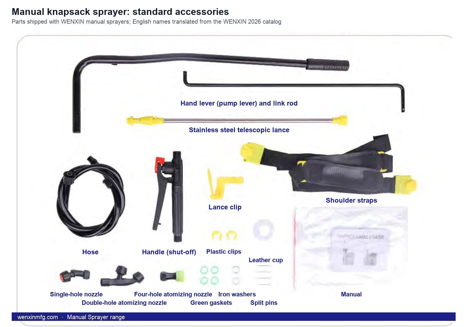
A manual knapsack sprayer diagram is short, because the operator supplies the power. Our 16 L and 20 L manual sprayers use a PP tank, work at 0.2–0.3 MPa and deliver 0.8–1.5 L/min over a 2–5 m range, and every unit ships with the same set of parts:
- Tank and lever: the tank sits on the operator’s back and the hand lever works the pump; the pump seal is a leather cup, and a leather cup and plastic clips come in the box.
- Hose and handle: the hose runs from the tank to a hand handle that opens and closes the flow.
- Lance and nozzles: a stainless steel telescopic lance with a single-hole nozzle, a double-hole atomizing nozzle and a four-hole atomizing nozzle; gaskets, iron washers, split pins and a lance clip complete the set.
- Straps: shoulder straps carry the tank.
Because a manual knapsack sprayer diagram has no engine, its spare-parts list is mostly seals and nozzles, which is what distributors stock first.
Which Parts Appear on an Electric Knapsack Sprayer Diagram?
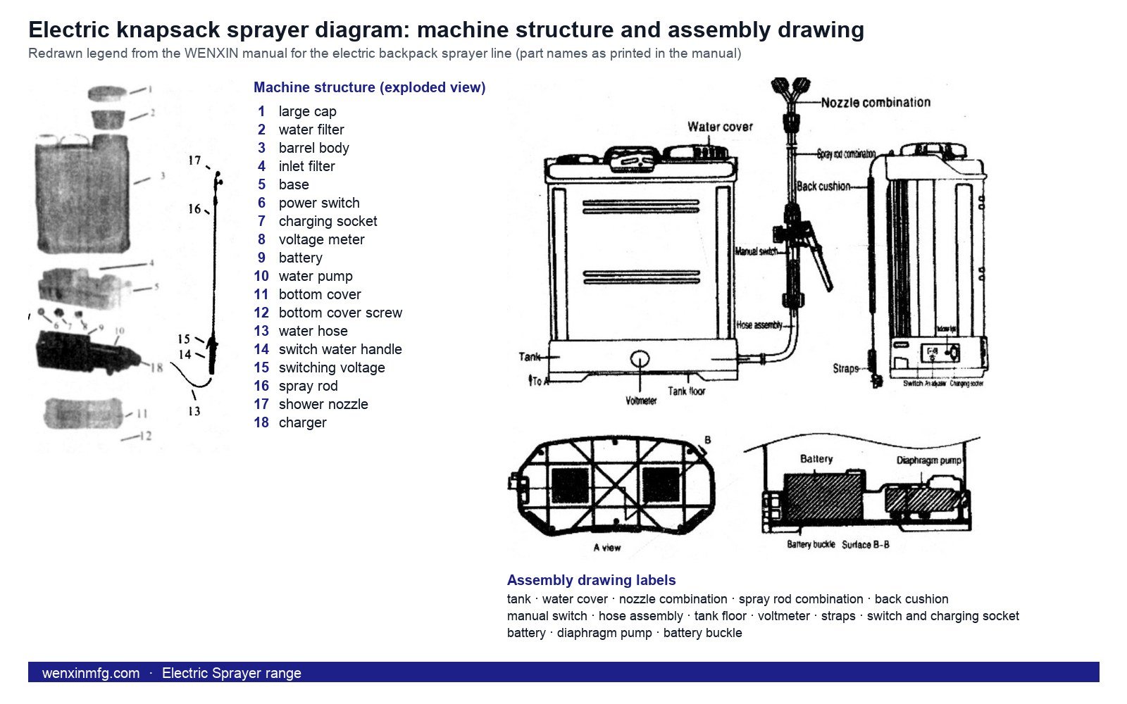
An electric knapsack sprayer diagram sits between the two: it keeps the tank, hose, lance and straps of the manual sprayer, but replaces the hand lever with a battery and a small water pump in the base. The structure diagram in our own manual for the electric backpack line names the parts in this order: large cap, water filter, barrel body, inlet filter, base, power switch, charging socket, voltage meter, battery, water pump, bottom cover and its screws, water hose, switch water handle, spray rod, shower nozzle and charger. The assembly drawing adds the back cushion, straps, tank floor and voltmeter, and shows the diaphragm pump and the battery buckle under the tank.
The troubleshooting table of that manual points to the same few parts when spraying weakens: a clogged or worn spraying sheet, a clogged filter screen, loose tube clamps at the pump, air left in the pump, or a battery short of power. So the spares list for an electric knapsack sprayer diagram is short: spraying sheets, filter screens, tube clamps and a charged battery.
Which Parts Appear on a Knapsack Power Sprayer Diagram?
The power version of a knapsack sprayer diagram adds an engine-pump module under the tank. On our range the tank holds 15, 20, 25 or 30 L depending on the model, and every model can be customized. The engine is one of four small gasoline (petrol) engines, the TU26, 34F, 139 or 35, from 25.6 to 35.8 cc and 0.7 to 0.85 kW. The pump is an aluminum pump head with an 18 mm plunger, working at 25–30 MPa, rated at 8 L/min and a 7–8 m spray range, the same across the line.
The standard configuration shipped with each unit, as listed in our catalog, is a 90 cm brass spray gun, an ordinary plunger, a strap, a switch box and a regular cushion. The switch box sits on the side of the tank and the cushion between the tank and the operator’s back. The 767 and the 8241 both offer 20 L and 25 L tanks with the four-engine choice; the full knapsack power sprayer range covers the other tank sizes.
How Does the Pump on a Knapsack Sprayer Diagram Work?
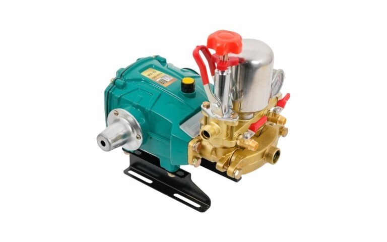
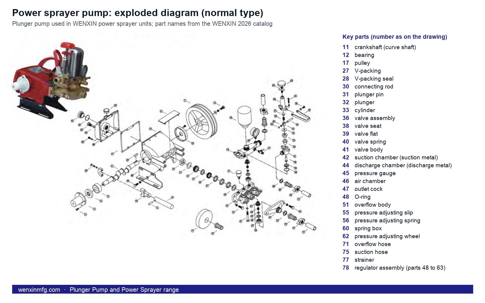
The pump is the part of a knapsack sprayer diagram that most people never see, so our catalog draws the pump of our power sprayer units exploded. The diagram below is that plunger pump; the knapsack pump is smaller but works on the same plunger principle, which we explain in how does a plunger pump work.
- Drive: a crankshaft on bearings turns in its case, and a connecting rod and plunger pin turn that rotation into the plunger’s back-and-forth stroke.
- Pressure: the plunger runs inside a cylinder sealed by V-packing; valves in the valve body let liquid in from the suction chamber and out to the discharge chamber, and an air chamber smooths the pulses.
- Control: a regulator assembly, an adjusting wheel on a spring and a slip, sets the working pressure; liquid above that pressure returns through the overflow body and overflow hose.
- Intake: a suction hose with a strainer keeps grit out of the valves.
When pressure drops, the strainer, V-packing, plunger and valves are all on this diagram; the nozzle is on the gun.
Which Parts on a Knapsack Sprayer Diagram Can Be Changed?
Not every part on a knapsack sprayer diagram is fixed. Our catalog lists these backpack options, among others:
- Plunger: ordinary, ceramic or stainless steel.
- Handle: standard controller, reinforced handle or stainless steel handle.
- Starter: ordinary pull plate, aluminum pull plate, multi-angle easy start or easy start versions.
- Switch and fittings: regular switch or plastic box switch; copper, aluminum or plastic elbow; a three-way and dual nozzles.
- Straps and cushions: regular back strap, brake strap, large-bend, double-S, leather or grid strap; regular, thickened or model-specific cushion.
The spray gun is the other swap: the 90 cm brass gun is standard, and alternative guns fit the same hose connection. A distributor can therefore standardize on one plunger and one strap for a market and treat the rest of the knapsack sprayer diagram as options.
How Do You Use a Knapsack Sprayer Diagram to Order Spare Parts?
A knapsack sprayer diagram is most useful when something breaks. Quote the part by the name on the diagram, together with the model, the tank size and the engine, and the spare can be matched without photographs going back and forth.
- Find the part on the diagram and use its name: plunger, V-packing, valve assembly, O-ring, strainer, nozzle, gasket, strap or cushion.
- Add the model, for example 767 or 8241, the tank capacity and the engine model.
- Say whether you want the standard part or one of the options above.
Seals and nozzles are the parts that go first, so a season’s stock of plunger seals, leather cups and nozzles covers most calls. Flushing the whole system the same day, as described in our guide on how to use a knapsack sprayer, keeps the rest of the knapsack sprayer diagram out of the workshop. For a parts list for your market, contact our sales team with the model and quantity.
What Do People Ask About Knapsack Sprayer Diagrams?
What are the main parts of a knapsack sprayer?
Tank, pump, hose, spray gun or lance with a nozzle, and straps. A manual sprayer pumps with a hand lever; a knapsack power sprayer replaces the lever with a gasoline (petrol) engine driving a plunger pump.
What is the difference between a manual and a power knapsack sprayer diagram?
The pressure group. The manual knapsack sprayer diagram shows a lever and a pump with a leather cup; the power version shows an engine and an aluminum plunger pump. The same kinds of parts, tank, hose, lance or gun and straps, appear on both.
Which knapsack sprayer parts wear out first?
The seals and the nozzle: the leather cup on a manual sprayer, the plunger seals on a power sprayer, and the nozzle and gaskets on both.
Can the spray gun on a knapsack sprayer be changed?
Yes. The 90 cm brass gun is the standard on our knapsack power sprayers and alternative guns fit the same hose connection; manual sprayers ship with a stainless steel telescopic lance and the nozzle set.
Sourcing sprayers, generators or water pumps?
Talk to the WENXIN factory team about specifications, customization and OEM orders.